2Using vernier calipers
How to read an analog vernier caliper to get precise measurements
Every part you design starts as a measurement of something real. This page covers the use of an analog vernier caliper in detail. You’ll use this tool a lot in the class!
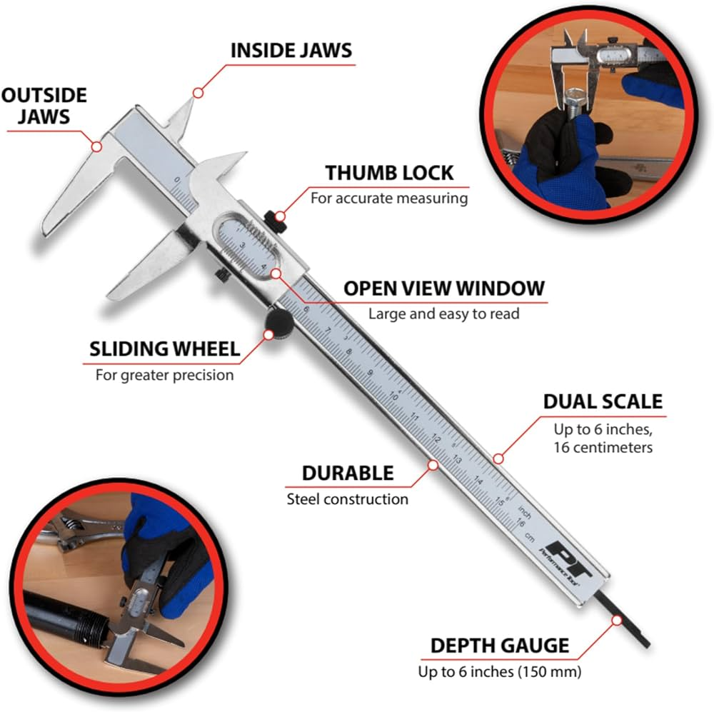
You will need
- An analog vernier caliper, you may need to share with a partner
- A small handheld part to measure
2.1Why not just use a ruler?#
Precision: Rulers are not the best for getting accurate measurements of 3D objects. You have to estimate the start and end of a dimension with a ruler and eyeball the result. A ruler also divides millimetres into halves at best, so the smallest thing you can honestly report from one is about 0.5 mm. A vernier caliper reads to 0.02 mm, which is twenty-five times finer.
2.2The parts of a caliper#
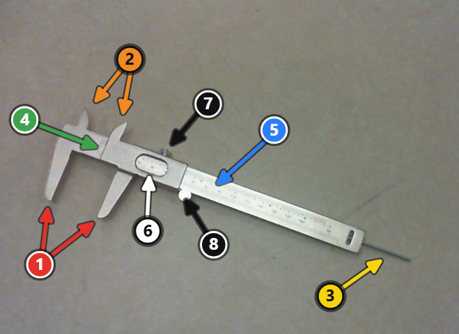
| # | Part | What it is for |
|---|---|---|
| 1 | Outside/big jaws | The large jaws at the bottom. Outside diameters, widths, thicknesses. |
| 2 | Inside/small jaws | The small jaws at the top. Inside diameters, slot widths, bores. |
| 3 | Depth rod | The thin blade that slides out of the tail. Hole and step depths. |
| 4 | Step face | The flat ledge behind the fixed jaw. Step and shoulder heights. |
| 5 | Main scale | The fixed scale, marked in whole millimetres. |
| 6 | Vernier scale | The short sliding scale, which gives you the fraction of a millimetre. |
| 7 | Locking screw | Holds the reading while you take the caliper off the work. |
| 8 | Thumb screw | Allows you to hold tension on the measurement by pushing this nub left (big jaws) or right (small jaws) |
The screw comes off. Do NOT lose it
The locking screw can be totally removed from the calipers. You never need to unscrew the lock all the way, but if it happens by accident, make sure you screw it back on tight. Losing the screw makes it easier for the calipers to fall apart or get damaged. These are expensive tools, so please treat them with care.
2.3How the vernier scale works#
The main scale is marked in millimetres. The vernier scale is marked so that its divisions are very slightly shorter than the main scale divisions. On a 10 division caliper, ten vernier divisions cover exactly 1 mm, so each vernier division is 0.1 mm.
2.4Taking a reading#
The reading is always two numbers, the main digit and your decimal.
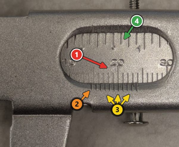
| # | Name | Description |
|---|---|---|
| 1 | Main Scale | These are the numbers in millimeters that go from 0 to 150, numbered with engravings every 10mm |
| 2 | Vernier Zero | This is the mark you use to measure the main scale at, and also the .0 tick on the vernier scale |
| 3 | Vernier Scale | 10 ticks (unnumbered) that represent the fractions of a millimeter |
| 4 | Imperial Scale | The top half shows the main scale in inches, which we will not be using for our course, so you can ignore it |
-
Read the main scale. Find the vernier’s zero mark. Read the largest whole millimetre on the main scale that is to the left of it. (Not the closest number) Write it down. If the vernier zero sits between 23 and 24, your main scale reading is 23 mm. Never round up. This should be similar to how you use a regular ruler.
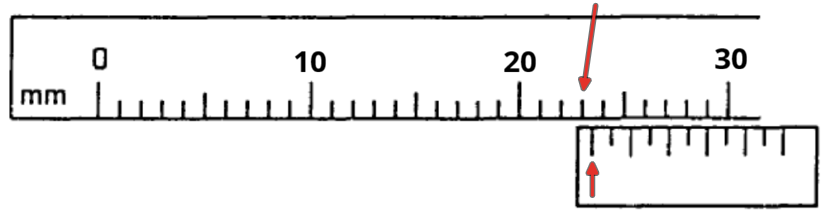
-
Read the vernier scale. Look along the vernier (the divisions on the window) for the one line that lines up perfectly with any line on the main scale. Only one will. The lines on either side of it will be slightly off.
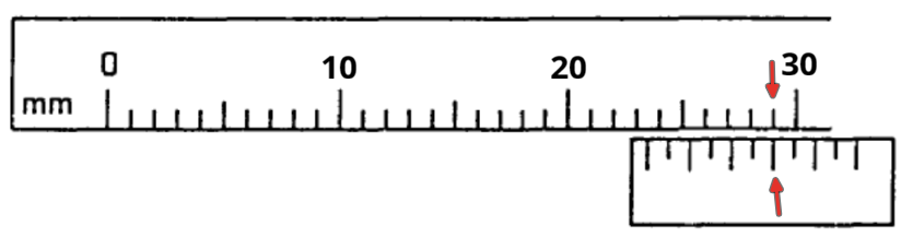
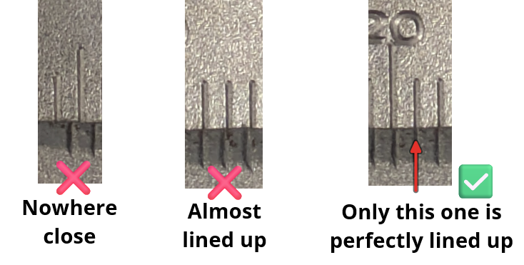
-
Convert the vernier reading. Count how many divisions along that line is, starting from the vernier zero, the left most line. If the 5th vernier line lines up with a digit on the main scale, that means the decimal reading would be 0.4mm. If the 7th line lines up with a digit on the main scale, the decimal reading would be 0.6mm. If the first and last lines both line up, it means your decimale reading is 0.0mm.
-
Add your two numbers together. e.g. main scale 23 mm + vernier scale 0.4 mm = 23.4 mm.
-
Write the number down on paper or enter it in the computer immediately. Don’t keep it in your head. You will forget it!
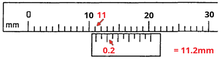
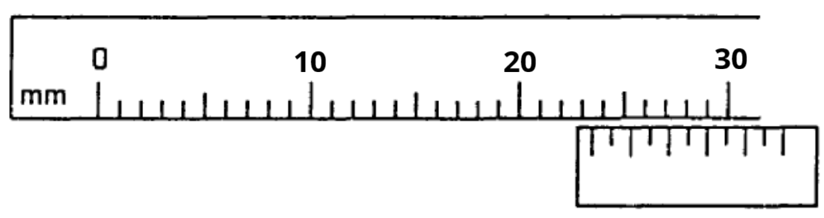
Example measurement - The first line on the vernier scale bottom ruler appears after the 11th tick on the main scale top ruler, which means this measurement is at least 11mm. The vernier scale's 3rd tick lines up perfectly with one of the lines on the main scale, which means it is 0.2mm since the first tick is 0.0, second tick is 0.1, third tick is 0.2. Add the two digits together to make 11mm + 0.2mm = 11.2mm as the final measurement.
Read it straight on
Look at the scale from directly above, not at an angle. Viewing a fine scale from the side shifts which line appears to align.
2.4.1Outside measurements#
-
Open the jaws wider than the part and slide the part fully between them, up against the fixed jaw.
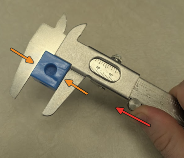
Part rests square inside of the jaws, light pressure is applied to the left with your thumb on the thumb screw -
Close the slide with your thumb on the thumb wheel until the jaws just touch the part. Light contact only. A caliper is not a clamp. Squeezing it compresses the object and gives you a reading that is too small.
-
Keep light pressure with your thumb (see image), then read the measurement. Write it down on a piece of paper, with the decimal and units (e.g. 24.5mm). Label this measurement as the cube’s width.
2.4.2Inside measurements#
-
Put the small upper jaws into a hole or divet and open them until they touch both sides.
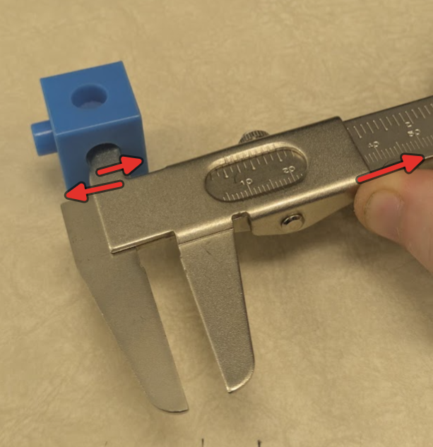
For circular measurements, rotate the jaws inside of the part to ensure you are getting the full diameter. The jaws should make square contact on the interior of the part. Light tension should be applied to the right using the thumb screw. -
Ensure the tips of the calipers are aligned correctly and opened as far as they can without stretching the part you’re measuring.
-
Keep light pressure with your thumb (see image), then read the measurement. Write it down on a piece of paper, with the decimal and units (e.g. 24.5mm). Label this measurement as the socket’s diameter.
2.4.3Depth measurements#
-
Sit the tail end of the main beam flat across the top of a surface with a hole or depth that can’t be measured with the jaws.
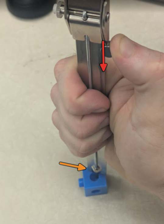
The base of the main scale should be square/flush/flat with the surface of the part you are referencing from. Light pressure is applied down using the thumb screw. -
Slide the caliper open so the depth rod runs down into the hole until it stops on the bottom.
-
Keep the tail flat on the surface the whole time. Ensure the tail end of the main beam is totally flat and flush with the surface. Tipping it is the usual source of error here.
-
Keep light pressure with your thumb (see image), then read the measurement. Write it down on a piece of paper, with the decimal and units (e.g. 24.5mm). Label this measurement as the socket’s depth.
2.4.4Step depth measurements#
This is an alternate way to collect depth measurements, only useful for when the part you’re measuring has a stepped face.
-
Rest the small ledge on the back of the fixed jaw on the lower surface of the part you’re measuring.
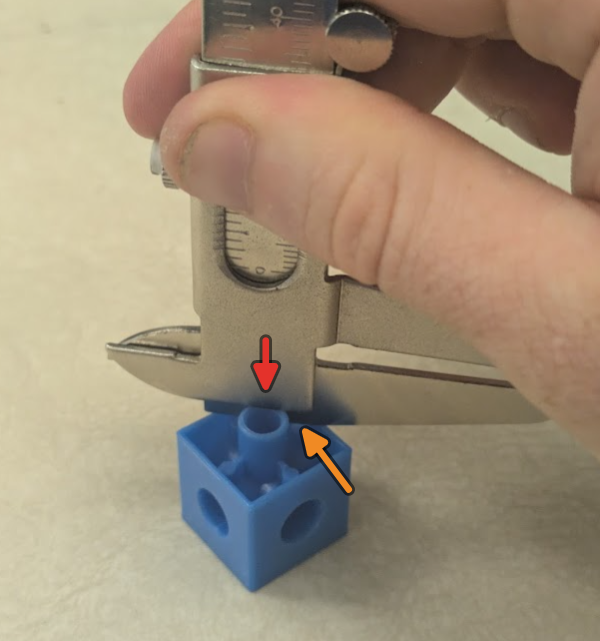
Move the jaws apart first, then place the left most jaw flush along the face you are referencing from. Slide the right jaw slightly up and then push down. The thumb screw is not used. -
Slide the moving jaw’s matching face down onto the upper surface.
-
Hold the calipers firmly, level against the ground, read the measurement. Write it down on a piece of paper, with the decimal and units (e.g. 24.5mm). Label this measurement plug’s protrusion distance.
2.5Habits that make a measurement trustworthy#
- Measure the same feature three times, taking the caliper off the part between each one. If the three readings agree to within 0.2 mm, you have a measurement. If they scatter by more than 0.3 mm, your technique is the problem, not the part.
- Record the number immediately. Do not carry it in your head across.
Calipers are instruments, not tools
Do not use a caliper as a scribe, a depth stop, a clamp, a pry bar or a screwdriver. Do not leave one on the floor, loose in a drawer with hand tools, or leave the lock screw loose.
2.6More Example Readings#
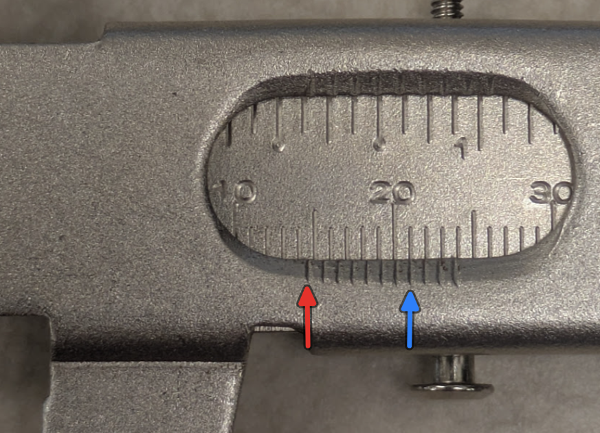
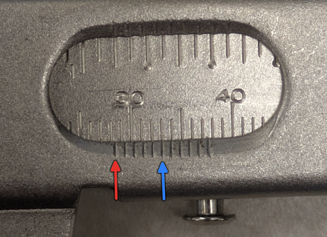
2.7Sign-off#
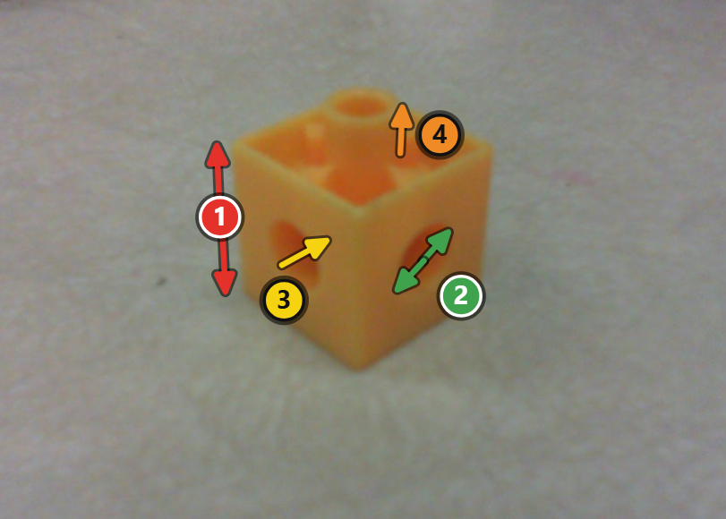
With the connecting cube, have all four dimensions measured accurate to 0.1mm on a piece of paper:
- Cube’s length: the height of the cube (big jaws)
- Socket diameter: the diameter of the socket hole (small jaws)
- Socket depth: the depth of the socket hole (depth rod)
- Plug’s protrusion distance: the distance of the plug from the flat surface (step depth)
2.8Level Up#
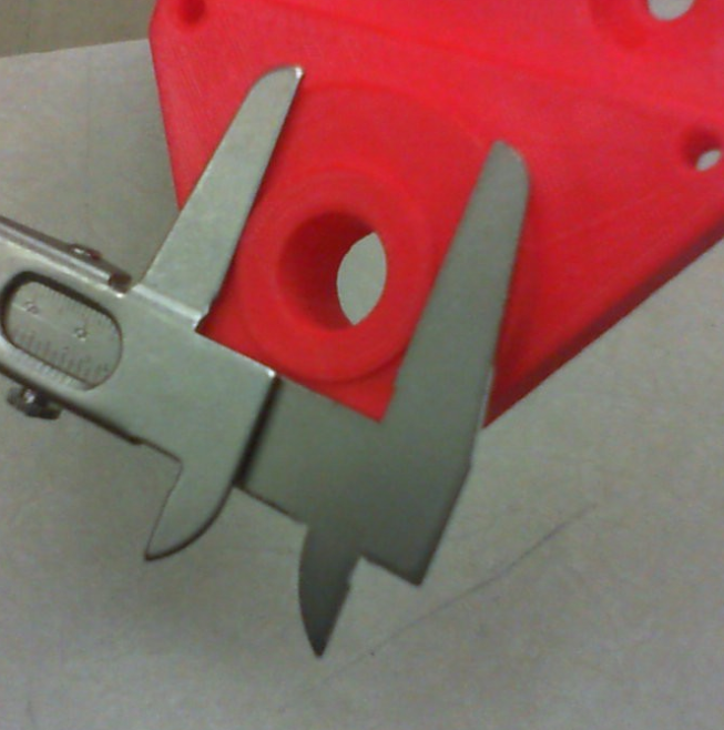
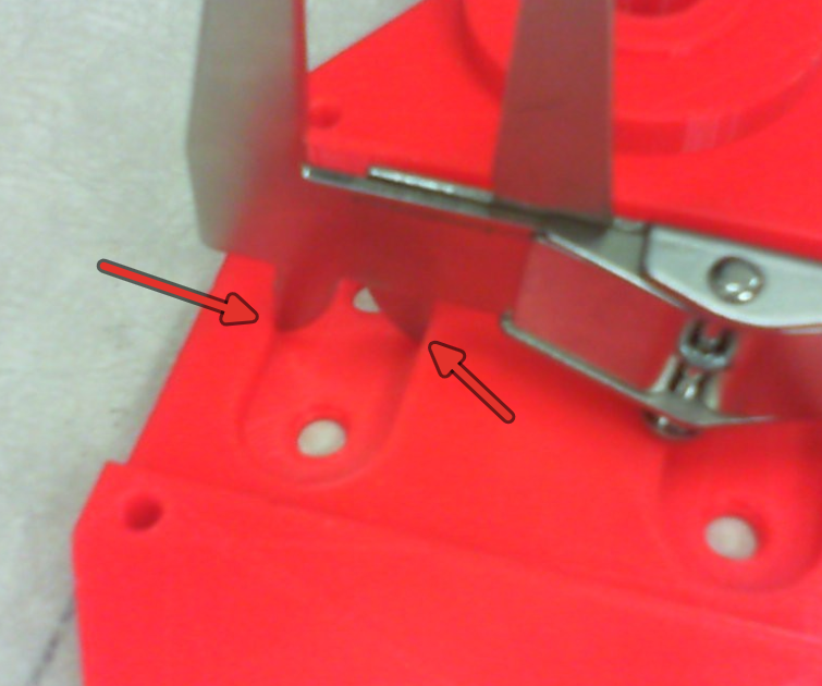
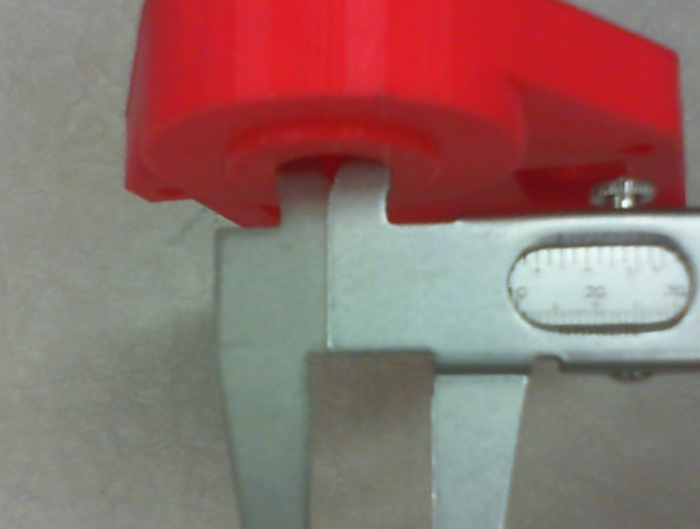
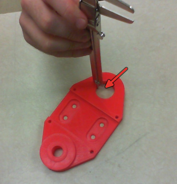
When you’re finished the connecting cube and want more practice, try collecting more complex measurements from other parts. Create a basic sketch of your object to record measurements.
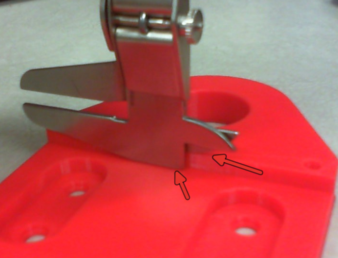
Here are some photos of example measurements from a 3D printed part:
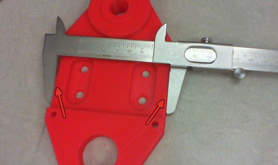
2.9Clean Up#
- Locking screw in place, jaws left slightly open
- Caliper back where it lives
- Any objects you were using to measure go back to where they live
- Any scraps of paper at your desk are thrown out or taken with you